Using the Alignment Tab
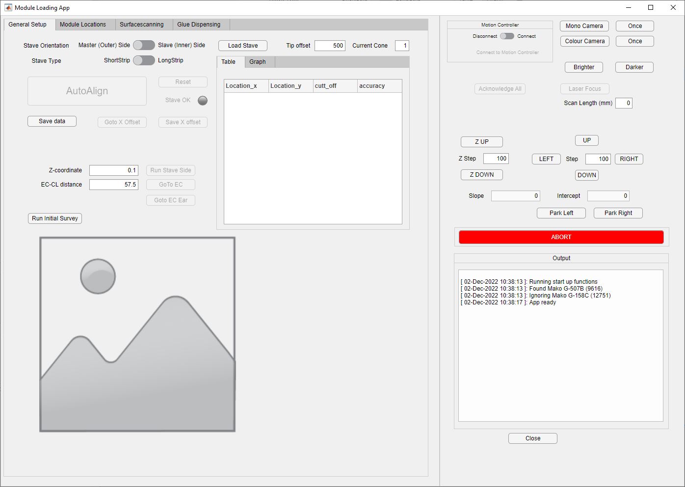
The view presented to the user on starting the Strip Tracker Module Loading software
When starting the module loading software, it initially makes no assumptions about alignment or anything. In future versions it may require a stave core number to be entered and might then load existing configurations, but currently operates purely based on dynamic recalibration after a restart.
The alignment procedure needs to be run in certain sequential steps:
Find all the cone features on the stave in machine coordinates
Fit a straight line through that (the stave-coordinate x-axis)
Find the z=0 edge of the stave in the middle of its surface
Together with the previous straight line, this defines a coordinate system on the stave core that aligns axes directions with the z-axis of ATLAS
Note: Alignment should be redone frequently, as microscopic movement during assembly will misplace modules.
Finding all locking point cone features
To automatically find all cone features on the stave core, the stave core should be properly seated within the assembly frame, which in turn should be butted up against the backstops and either the right (Master side) or left (Slave side) stop, so that the initial position on the table is within certain limits.
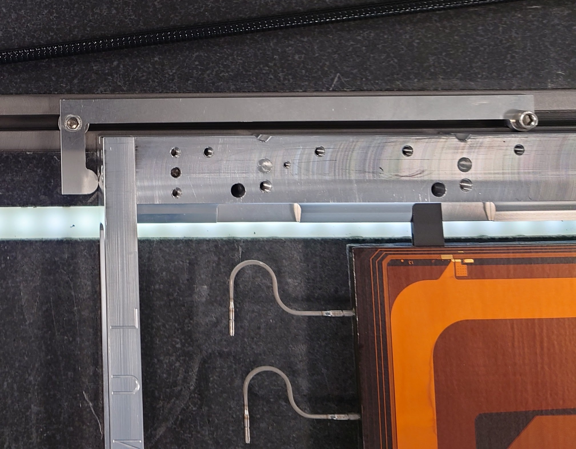
The stave within the assembly frame needs to be pushed against the backstop and then slide with the cooling pipe end against the corresponding endstop.
After starting the software, it needs to connect with the gantry system. To do so, flip the connect/disconnect switch in the gantry half of the software to connect. The user should then select the stave side that they are currently looking at/intend to align (using the switch at the top of the align tab). Once connected and with the stave to be loaded configured correctly, click the Reset button to align the gantry to a nominal location of the first cone shape used for alignment. To avoid complications during alignment it is helpful to only start the camera after arriving in the reset location. To start the monochromatic camera hit the “Mono” button in the top right. You should now be seeing the z=0 side of the z=0 lockpoint, hopefully aiming at the tip of the lockpoint cone shape. If that is not the case, use the left/right/up/down buttons in the right-hand section of the GUI to align to the tip of that first cone. Now you can hit the AutoAlign button and the gantry should (fingers crossed) proceed along the stave to identify fiducial markers.
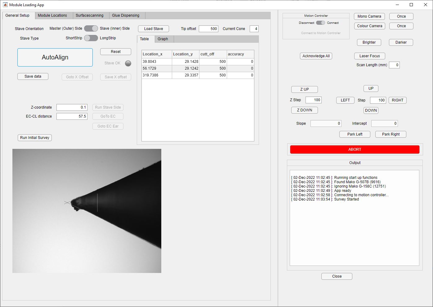
Strip Tracker Loading Software running an automated alignment procedure.
If automatic lighting causes trouble (usually on the first pattern), pattern-recognition might fail, which will be reported in the log textbox on the lower right of the application. Should that happen, then just press the AutoAlign button again, and things should start moving.
The gantry will automatically drive to reasonably good positions without any reference to the object itself, so the stave should be well aligned against the backstops to provide good images for the pattern recognition. Once all cones have been sampled, a straight line fit is performed, deriving the best respresentation of a lock-point axis. This will be used for all further identification of the long axis of the stave. To derive a full coordinate system, the gantry will the return to the z=0 end of the stave and point the camera to the position which should reflect the z=0 edge of the upward stave face. We reference this corner of the facing to make sure that modules do not overhand the edge:
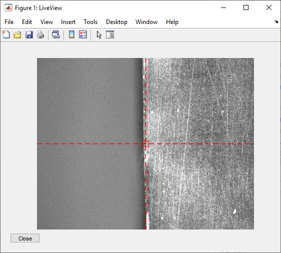
Strip Stave at z=0 end. The edge of the stave that is used as the 0 coordinate is visible in the middle of the picture.
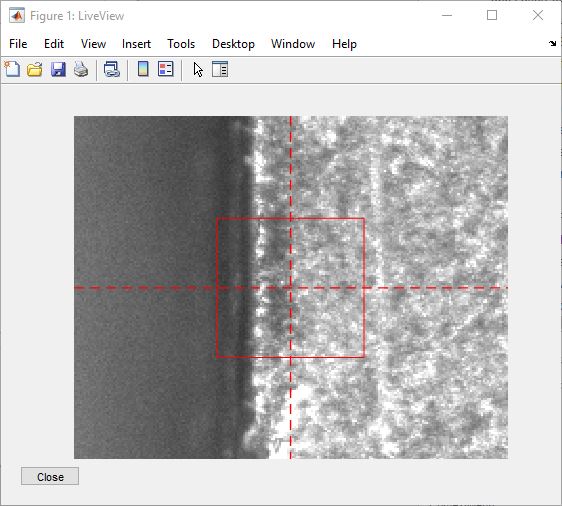
Strip Stave at z=0 end. Zoomed view of the previous figure.
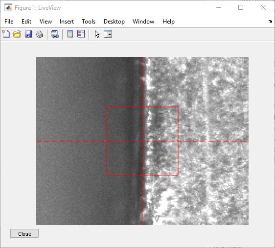
Strip Stave at z=0 end. Adjusted to the nominal edge (some of that is subjective, but red square is 100x100 um total dimension)
If not placed within the centre of the mono camera view, the User can use the Left and Right buttons in the alignment view (which are only available after running the automatic alignment) to move along the stave long axis (left/right) in definable steps (micrometer). Once the edge is aligned with the red crosshair, to save the Offset for the X-axis, press the Save X Offset button. The gantry will now automatically drive to where the closeout corner should be. Note that if the corner is far away from the midpoint of the mono camera view (see following picture), then this shall be recorded in a log and brought to the attention of the stave core production site, as this may cause problems during insertion. The previously used left/right as well as the up/down buttons can be used to identify the distance between the nominal position and the actual.
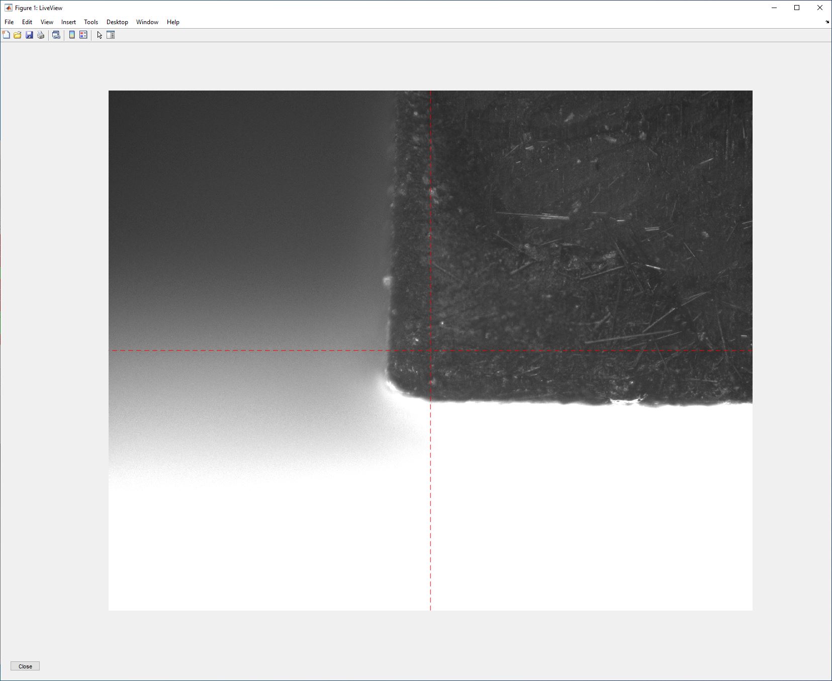
Closeout corner at z=0, in this case for a slave side, so on the lockpoint edge of the stave. This particular one is out of spec and should be flagged.
At this point the gantry has fully aligned to the stave core and can thus perform operations based on the stave core coordinate system, i.e. point to or survey specific objects/fiducials, spread glue at specific positions and to specific patterns, or load and align modules.